


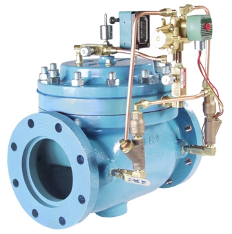
The OCV Series 125 and 126 Pump Control Valves are designed to effectively eliminate the surges associated with the starting and stopping of the pump. Electrically interfaced with the pump motor, the valve opens and closes at an adjustable speed, providing a smooth, predictable transition of pump discharge pressure and volume into the system.
| Model | Model Sheet | Model Sheet (metric) | Specifications | Animation | Operations Manual |
|---|---|---|---|---|---|
| Model 125 Booster Pump Control Valve |

|

|

|
||
| Model 125-7 Booster Pump Control Valve |
|
|
|
||
| Model 125-27 Booster Pump Control Valve |
|
|
|
||
| Model 125-27P Booster Pump Control Valve Dual Chamber/Lift Check/High Pressure |
|
|
|
||
| Model 126 Deep Well Pump Control Valve |
|
|
|
||
| Pump Commander |
|
|
Models 125 and 125-27, designed primarily for booster pumps, are installed inline, on the discharge of the pump. These valves also include a check feature that eliminates any need for a separate pump check valve.
Model 126, designed for deep well pumps, is installed on a bypass line between the pump discharge and the pump check valve. The Model 126 eliminates debris and air on pump start.
Model 125 and 125-27, designed primarily for booster pumps, are installed inline, on the discharge of the pump. They are normally closed with the pump off, open slowly after the pump starts, and close slowly prior to pump shutdown. In this way, flow is slowly and smoothly transitioned to and from the system. These valves also include a check feature that will close the valve in the event of a power failure while the pump is running. Thus, they eliminate any need for a separate pump check valve.
Model 126, designed for deep well pumps, is installed on a bypass line between the pump discharge and the pump check valve, and discharges either to waste or back into the well itself. It is normally open with the pump off, closes slowly after the pump starts, and opens slowly prior to pump shutdown. In this way, flow is slowly and smoothly transferred from the bypass to the system, and vice-versa.
A certain amount of components and wiring is required to interface the valve and pump. The wiring diagram below is typical for Series 125. Series 126 is similar but with minor variation to the limit switch. (consult factory for specific diagram) To make the interface quick and simple, the OCV Pump Commander may be added to your installation. This pre-wired controller is available in various models depending upon the level of control sophistication required.
Series 125;
SOL = SOLENOID PILOT (ON VALVE)
LS = LIMIT SWITCH, SPDT (ON VALVE)
CR1,CR2 = CONTROL RELAY, DPDT
TD1* = TIME DELAY RELAY, DPDT, ON-DELAY
TD2** = TIME DELAY RELAY, DPDT, ON-DELAY (OPTIONAL)
HOA = HAND-OFF-AUTO-SWITCH
RS = REMOTE START SWITCH
MSR = PUMP MOTOR STARTER RELAY
*TD1 shuts pump down if valve does not open
**TD2 if used, delays valve opening for predetermined time period
By combining various control pilots, multiple valve functions can be performed on a single Series 125 or 126 Pump Control Valve. To find the combination function valve, select the desired features and then the model number. This chart shows only a sample of those most often specified valves. Consult the factory for specific data on the model you selected.
Combination valves can often reduce or eliminate other equipment. Example: If the system requires a Pump Control and a Pressure Sustaining Valve, the sustaining feature can be added as a function of the Pump Control Valve, Model 125-13.
Selecting and sizing the correct model of pump control valve begins with the pump itself. Refer again to Table 1.
Pumps such as split-case centrifugals or flooded suction turbines, commonly referred to as booster pumps, will use the Series 125.
Well pumps, such as vertical turbines or submersibles, may use either the Series 125 or the 126. To determine which, first consult with the pump manufacturer. If the pump is designed to start against a closed valve, use the Series 125. If the pump is designed to be started against an open valve, the choice is Model 126. If there is no preference, consider the characteristics of the well itself. Deeper wells, those with a significant air column, and those producing a significant amount of sand will benefit most from the Model 126. Relatively shallow, clean wells can use the Series 125.
If you have opted for the Series 125 booster pump control valve, your next step will be to choose between the single-chambered 125 and the dual-chambered 125-27. Certain factors can make this choice an easy one. For example, if you want to add modulating control pilots to the valve (e.g, pressure reducing, pressure sustaining), or if the maximum pressure (typically pump shut off pressure) is greater than 400 psi, your only choice will be the single-chambered valve. On the other hand, the chief advantage of the 125-27 is that of typically lower pressure loss. Now the choice is closely tied in with sizing.
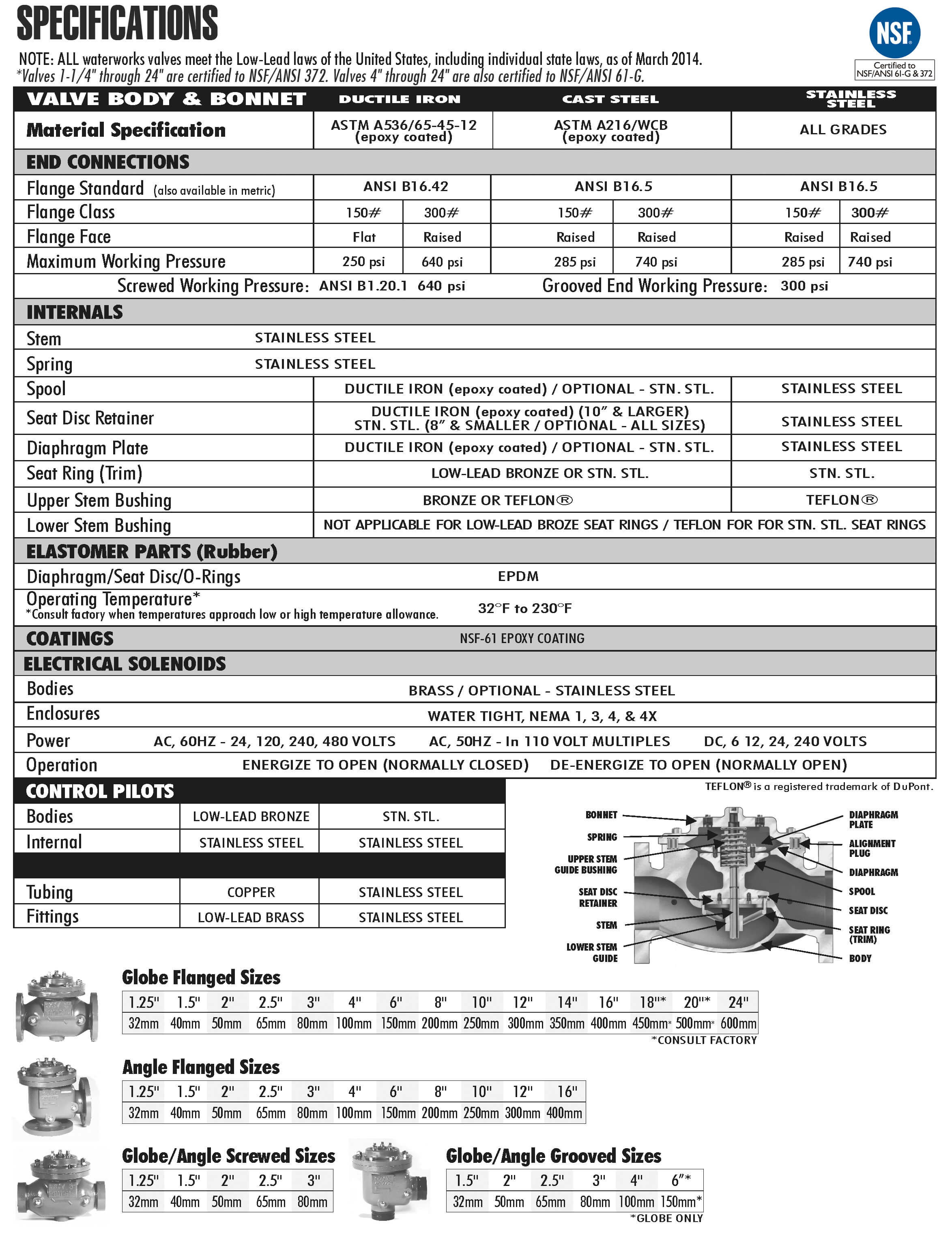
For maximum efficiency, the OCV control valve should be mounted in a piping system so that the valve bonnet (cover) is in the top position. Other positions are acceptable but may not allow the valve to function to its fullest and safest potential. In particular, please consult the factory before installing 8″ and larger valves, or any valves with a limit switch, in positions other than described. Space should be taken into consideration when mounting valves and their pilot systems.
A routine inspection & maintenance program should be established and conducted yearly by a qualified technician. Consult our factory @ 1-888-628-8258 for parts and service.
When Ordering please provide:
Series Number – Valve size – Globe or Angle – Pressure Class – Screwed, Flanged, Grooved – Trim Material – Adjustment Range – Pilot Options – Special needs / or installation requirements.