

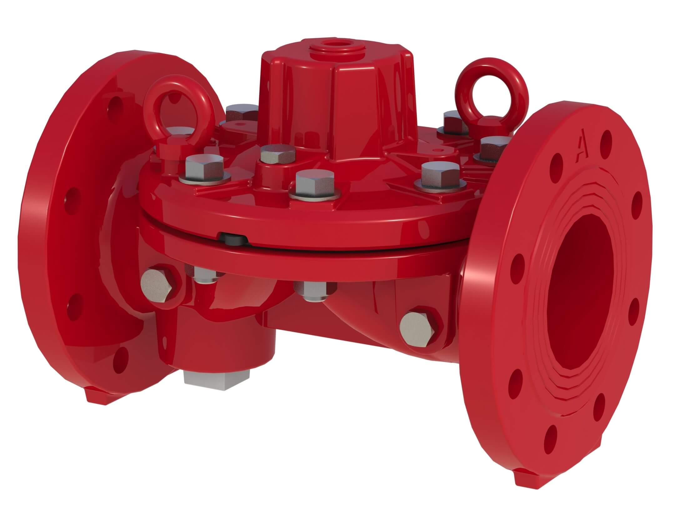
The OCV Series 100 control valves are automatic, hydraulically actuated, direct diaphragm sealing globe/weir type valves with a proven and reliable design. These valves are designed for use in fire protection applications including deluge, pre-action, pressure relief, monitors, hydrants and are suitable for water, foam and seawater systems. The valves consist of three major components: body, cover and diaphragm assembly.
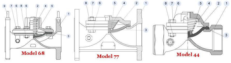
UL Listed basic untrimmed valve models: 44, 68, 77
Model 44: Up to 230psi working pressure, threaded.
Model 68: Up to 375psi working pressure, flanged & grooved with drain port.
Model 77: Up to 230psi working pressure, flanged & grooved.
• UL Listed under the following categories:
– “Special Systems Water Control Valves” Deluge (VLFT) – Model 68
– “Fire Pump Pressure Relief Valves” (QXZQ) – Models 44 & 77
• ABS Design assessment & Fire tested to EN ISO 6182-5:2006 – Model 68 2”-6”
• Lloyd’s type approval
• CCCf – Model 68 DE\EL(CN)
• GOST-R
• Manufacture & conformity assessment of pressure equipment & assemblies Directive (97/23/EC / EN1074)
Consult the UL listing guide or contact Aquestia USA for a complete list of approved applications and valve sizes.
STANDARD
• Listed & approved for use in fire protection systems by various global standards
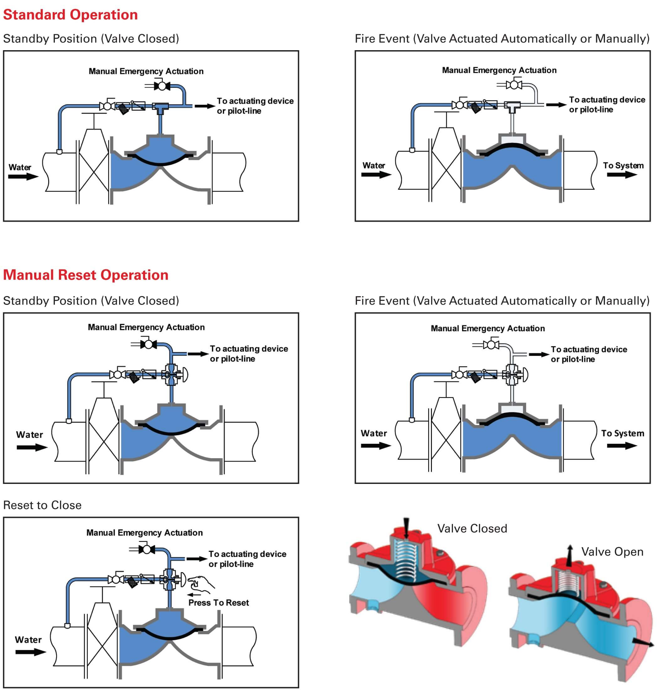
• Quick opening: Non-slam closing operation
• Drip-tight shut off to ANSI FCI 70-2 VI seat leakage class
• Simple and reliable design
• Low lifelong maintenance costs due to straightforward design
• Easy installation and inline maintenance
• High-grade construction materials
• Exceptionally low pressure losses
OPTIONAL
• Remote or manual reset
• Manual, electric, hydraulic, pneumatic and combined control trims
• Explosion proof, SIL redundant solenoids & trim accessories
• Seawater and foam concentrate service
Model 68 shown. Same principle of operation is applicable for Models 44 & 77.
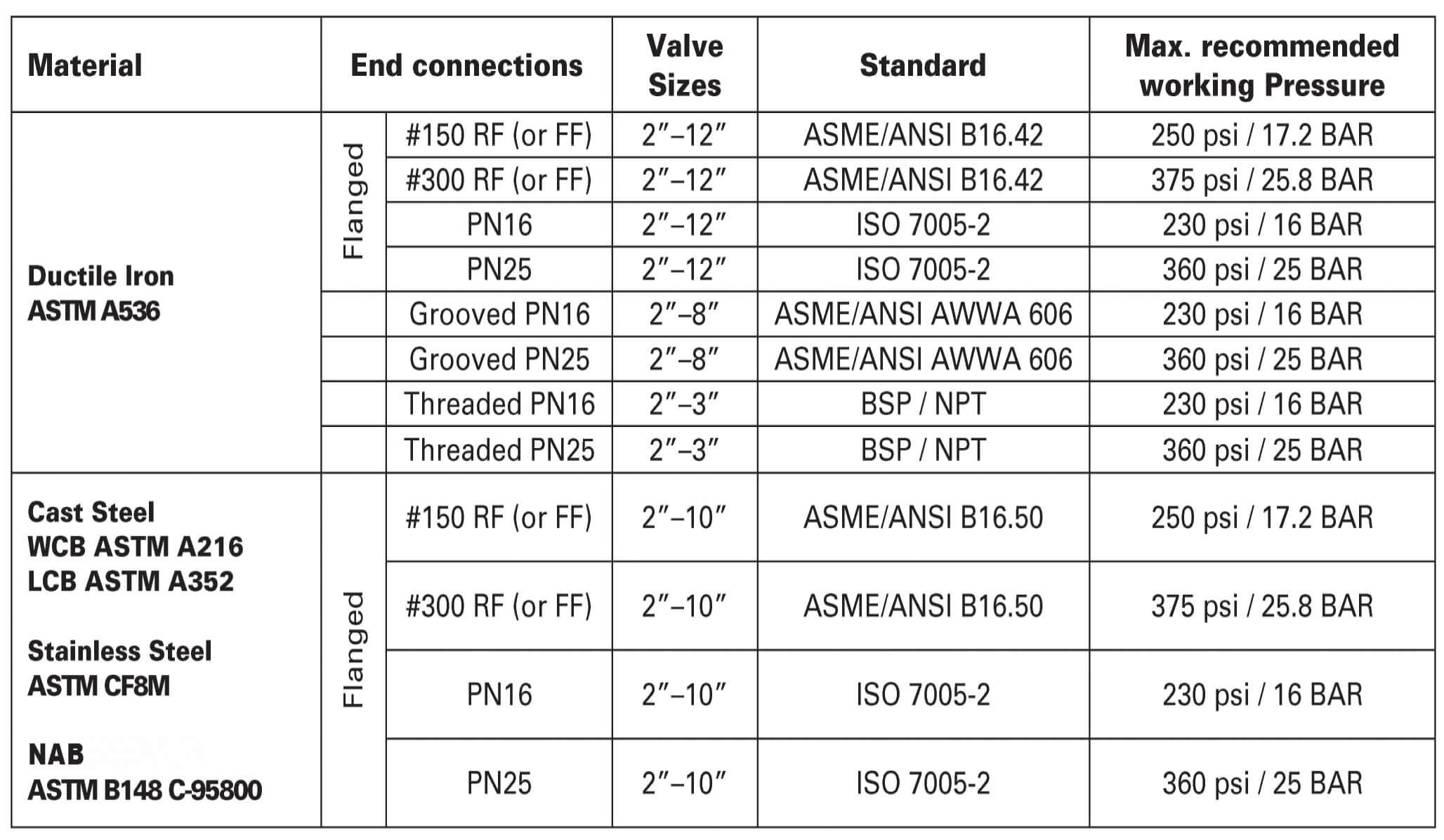
PRESSURE RATING
Recommended nominal system pressure to flange class for typical materials as:
• 250psi nominal system pressure for flanges ANSI B16.42 & ANSI B16.50 Class #150 accordingly.
• 375psi maximal system pressure for flanges ANSI B16.42 & ANSI B16.50 Class #300 accordingly.
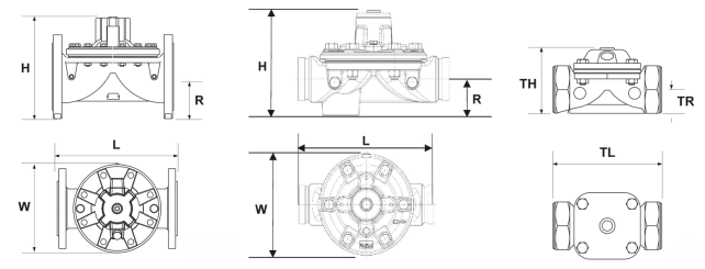
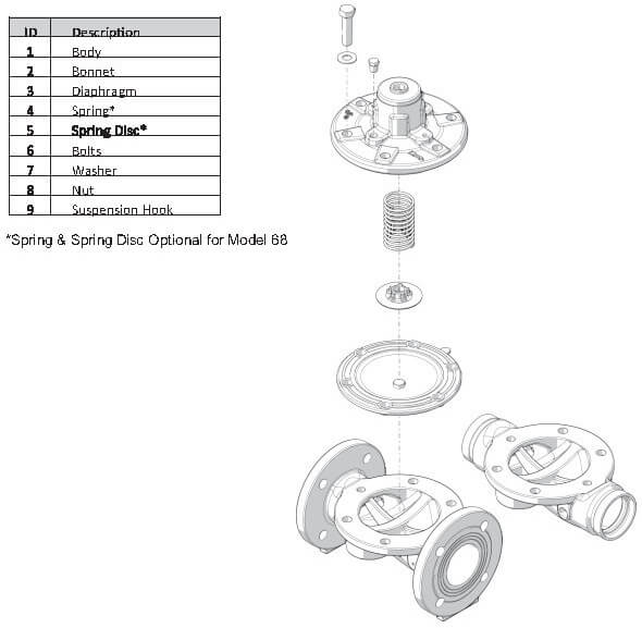
COMPONENTS
SPECIFICATIONS
Temperature:
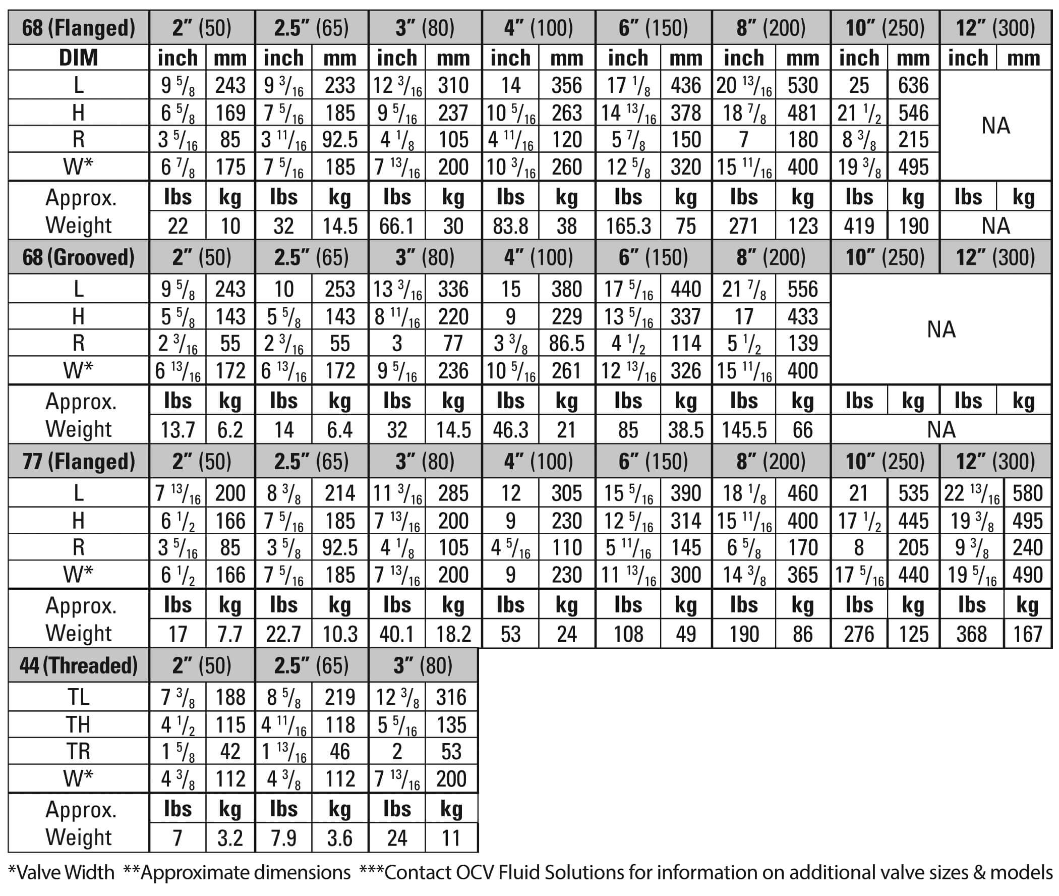
Sizes:
End Connections:
Body & Cover Material:
Coating Material:
Optional Coating Material:
Internal Trim Material:
Elastomers:
Control Trim & Accessories:
Optional Components: