


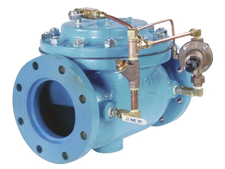
In many liquid piping systems, it is vital that line pressure is maintained within relatively narrow limits. This is the function of the 108 Pressure Relief / Back Pressure Series of the OCV control valves. Installed in the main flow line, the standard Model 108-2 acts as a backpressure or pressure sustaining valve. In this configuration, the valve maintains a constant upstream pressure regardless of fluctuating downstream demand. When used in a bypass line, the same model will function as a relief valve, protecting the system against potentially damaging surges.
| Model | Model Sheet | Model Sheet (metric) | Specifications | Animation | Operations Manual |
|---|---|---|---|---|---|
| Model 108-2 Pressure Relief/ Pressure Sustaining Valve |

|
|

|
||
| Model 108-2HP Pressure Relief/ Pressure Sustaining Valve |
|
|
|||
| Model 108-3 Pressure Relief/ Pressure Sustaining and Check Valve |
|
|
|
||
| Model 108-4 Pressure Relief/ Pressure Sustaining and Solenoid Shut-Off Valve |
|
|
|
||
| Model 708-2 Reduced Port Pressure Relief/ Pressure Sustaining Valve |
|
|
Protects system from overpressure by exhausting excess pressure. The valve may only have to operate intermittently to prevent pressure surges that might occur on pump start, pump stop, or sudden downstream valve closure.
Valve keeps pumping system at a constant pressure by bypassing back to source. Provides accurate pressure control when system demand varies widely
Valve allows flow when inlet pressure is above the set-point thus preventing inlet pressure from falling too low. Prevents demand from “robbing” the source, or keeps pump “on its curve.”
RELIEF VALVE – Closed under normal operating pressures. Valve opens when pressure rises to the set point. Valve will close when system pressure drops below set point.
BYPASS PRESSURE CONTROL VALVE – Opens and modulates to maintain the required pressure.
BACKPRESSURE / SUSTAINING VALVE – Open under normal conditions and closes as upstream pressure falls below set point.
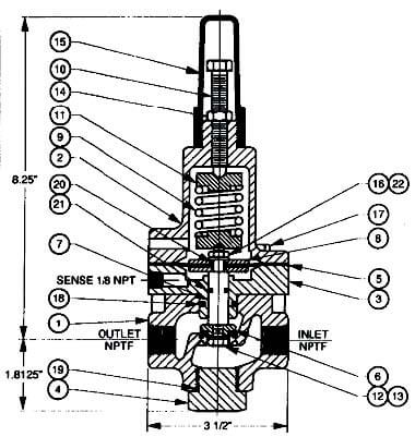
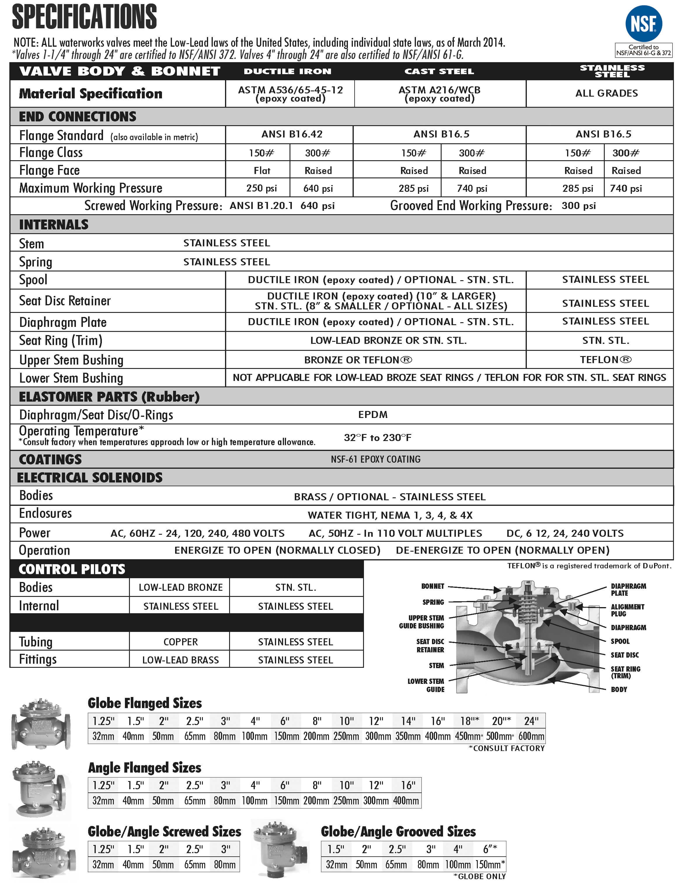
The Model 108-2 consists of the following components, arranged as shown on the schematic diagram:
1.) Model 65 Basic Control Valve, a hydraulically-operated, diaphragm-actuated, globe or angle valve which closes with an elastomer-on-metal seal.
2.) Model 1330 Pressure Relief Pilot, a two-way, normally-closed pilot valve which senses upstream pressure under its diaphragm and balances it against an adjustable spring load. An increase in upstream pressure tends to make the pilot open.
3.) Model 126 Ejector, a simple “tee” fitting with a fixed orifice in its inlet port. It provides the proper pressure to the diaphragm chamber of the main valve depending on the position of the pressure relief pilot.
4.) Model 141-3 Flow Control Valve, a needle-type valve which provides adjustable, restricted flow in one direction, and free flow in the opposite direction. On the 108-2, the flow control valve is connected as a closing speed control.
5.) Model 159 Y-Strainer (standard on water service valves) or Model 123 Inline Strainer (standard on fuel service valves). The strainer protects the pilot system from solid contaminants in the line fluid.
6A / 6B.) Two Model 141-4 Ball Valves (standard on water service valves, optional on fuel service valves), useful for isolating the pilot system for maintenance or troubleshooting
Pilot Materials
Low-Lead Bronze
Stainless Steel
Spring Ranges
5-30, 20-80, 20-200, 100-300 psi
Pilot Materials
Stainless Steel
Spring Ranges
200-750 psi
The Model 1330/2400 Pressure Sustaining Pilot controls the amount of pressure in the upper chamber of the Main valve(s). (Hence, the degree of opening or closing of the Main valve). The upstream pressure increases, the pilot begins to open, decreasing the amount of pressure in the upper chamber of the main valve allowing it to open a proportionate amount, in order to maintain a constant inlet pressure. As the upstream pressure decreases, the pilot begins to close, allowing the pressure in the upper chamber of the main valve to increase causing it to close. This is a constant modulating action compensating for any change in upstream pressure.
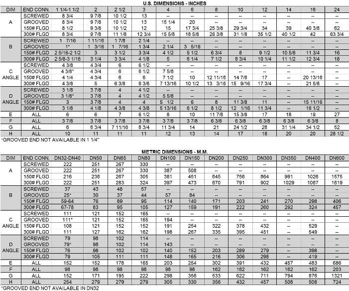
For the most comprehensive procedure in sizing Series 108 control valves, it is best to use our ValveMaster software or the guidelines shown here in conjunction with the Performance Charts in the Engineering Section of the OCV catalog.
Bypass pressure control valves are sized based on maximum flow and pressure drop across the valve. The maximum flow through the valve is the pump flow at the desired set point (from the pump curve) minus the minimum system flow. The pressure drop across the valve is the set point minus the pressure at the valve discharge (typically pump suction or storage tank head). Determine the valve’s operating Cv using the maximum flow and pressure drop from the formula:
From the chart below, pick the smallest valve that has at least the Cv determined above, and where the velocity does not exceed 25 ft/sec.
Size is determined by the amount of flow required to lower the inlet pressure. This relief flow can be difficult to determine, so a general guideline is to use 60% of the rated pump flow. The 108 Series valve is capable of intermittent flows up to 45 ft. per second. Relief valve sizes are typically 50-60% of the mainline size.
Sustaining valves are typically main line size. However, maximum velocity through the valve should not exceed 25 ft/sec.
Many surge relief, and some bypass pressure control valves are, by their application, subject to pressure differentials that may induce cavitation. When these conditions exist, it may be only on an intermittent basis, causing minimum concern for valve deterioration.
This complex phenomenon cannot be predicted by charts, which index only inlet and outlet pressures. The easiest way to predict cavitation is to let us do the calculation. Simply fax, e-mail or call us and we will provide a graphical analysis and a solution. Provide us:
APPLICATION (e.g., surge relief, bypass pressure control)
VALVE SIZE
PRESSURE-INLET and OUTLET
FLOW RANGE-Minimum and Maximum
FLUID TYPE
FLUID VAPOR PRESSURE (if other than water)
By combining various control pilots, multiple valve functions can be performed on a single Series 108 Pressure Relief Valve. To find the combination function valve, select the desired features and then the model number. This chart shows only a sample of those most often specified valves. Consult the factory for specific data on the model you selected.
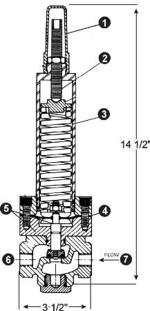
When valve inlet pressure requires the model 2400 High Pressure Relief pilot, an HP is added to the end of the model number. Example: Standard model 108-2 (inlet ranges from 5 – 300 psi) Model 108-2HP (outlet ranges 200-750 psi)
Surge Anticipation refer to series 118
For maximum efficiency, the OCV control valve should be mounted in a piping system so that the valve bonnet (cover) is in the top position. Other positions are acceptable but may not allow the valve to function to its fullest and safest potential. In particular, please consult the factory before installing 8″ and larger valves, or any valves with a limit switch, in positions other than described. Space should be taken into consideration when mounting valves and their pilot systems.
A routine inspection & maintenance program should be established and conducted yearly by a qualified technician. Consult our factory @ 1-888-628-8258 for parts and service.
When Ordering please provide:
Series Number – Valve size – Globe or Angle – Pressure Class – Screwed, Flanged, Grooved – Trim Material – Adjustment Range – Pilot Options – Special needs / or installation requirements.