


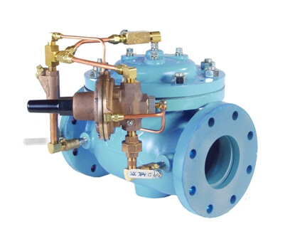
The OCV Series 120 Rate of Flow Control Valves is designed to control or limit flow to a predetermined rate, regardless of fluctuations in downstream or upstream pressure.
| Model | Model Sheet | Model Sheet (metric) | Specifications | Animation | Operations Manual |
|---|---|---|---|---|---|
| Model 120 Rate of Flow Control Valve |

|

|

|
||
| Model 120-1 Rate of Flow Control/Solenoid Shut-Off Valve |
|
|
|
||
| Model 120-2 Rate of Flow Control Valve and Pressure Reducing Valve |
|
|
|
||
| Model 128 Excess Flow Shut-Off Valve |
|
|
Where two water districts are connected, the valve limits flow rate between the two.
Installed in the backwash line, the valve limits flow rate during the backwash cycle to prevent filter media blow out.
The OCV Model 128, excess flow shut-off valve closely resembles the standard model 120 Rate-of-Flow control valve. However, in place of the previously described rate of flow pilot model 2450, the 128 is equipped with an adjustable, spring-loaded, locked-open pilot that is non-modulating (model 1380). As long as the differential pressure across the orifice plate (flow rate) is less than the pilot setting, the valve remains open. Should the orifice plate differential exceed the setting of the pilot, the pilot “trips” closed and fully closes the main valve. The pilot and main valve remain closed until manually reset.
The OCV Model 128 is therefore valuable in protecting against a break in the downstream pipe.
Model 1380 Excess Flow Pilot Material of Construction: Stainless Steel
Orifice Plate: Stainless Steel
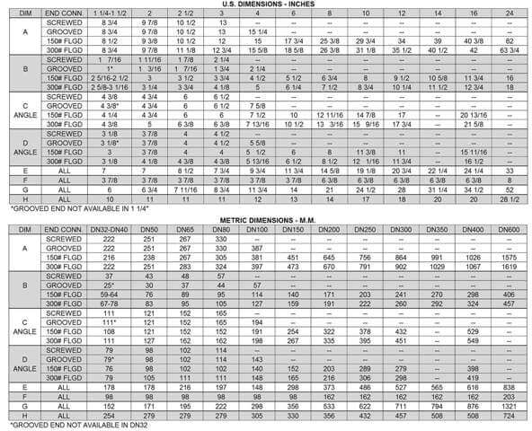
Based upon standard orifice plate bore size with water as the flowing media. Consult factory for other liquids and flow rates.
![]()
Using the flow characteristics chart above, select the size where the design flow rate comes closest to the middle of the flow range shown. For example, for 300 gpm, the best size would be a 3″.
Sometimes a valve selected in this manner will be less than line size, and there may not be room for reducers. By changing to a small-than-standard orifice plate, larger valves can be used at lower flow rates than those shown. Consult factory for details. For a comprehensive guide to sizing, refer to OCV ValveMaster Sizing & Selection software.
The 120 is furnished fully factory-assembled and ready for installation at the appropriate point in the system. Install the valve referencing the flow arrow tag. The orifice plate will be in the inlet flange. It is recommended that at least five diameters of straight pipe be allowed upstream of the valve.
The model 2450 is a normally-open, double-acting, spring-loaded, diaphragm pilot valve (see illustration). Control piping provides for sensing differential pressure across the valve inlet orifice plate. The upstream (high pressure) side is sensed under the pilot diaphragm; the downstream (low pressure) side over the diaphragm. Closing of the pilot is assisted by the adjustable spring. Flow rate may be changed by the adjusting screw. The pilot is adjustable within a 4:1 ratio, depending on the orifice size used. Variations in pressure differential across the orifice plate produce modulation in the double-acting pilot, which in turn creates a mirror-modulation in the main valve. Increased differential pressure works to close the valve while a drop in such pressure opens it.
By combining various control pilots, multiple valve functions can be performed on a single Series 120 Rate-of-Flow Control Valve. To find the combination function valve, select the desired features and then the model number. This chart shows only a sample of those most often specified valves. Consult the factory for specific data on the model you selected.
Combination valves can often reduce or eliminate other equipment. Example: If the system requires a Pressure-Reducing function, the feature can be added as a function of the Rate-of-Flow Valve, Model 120-2.
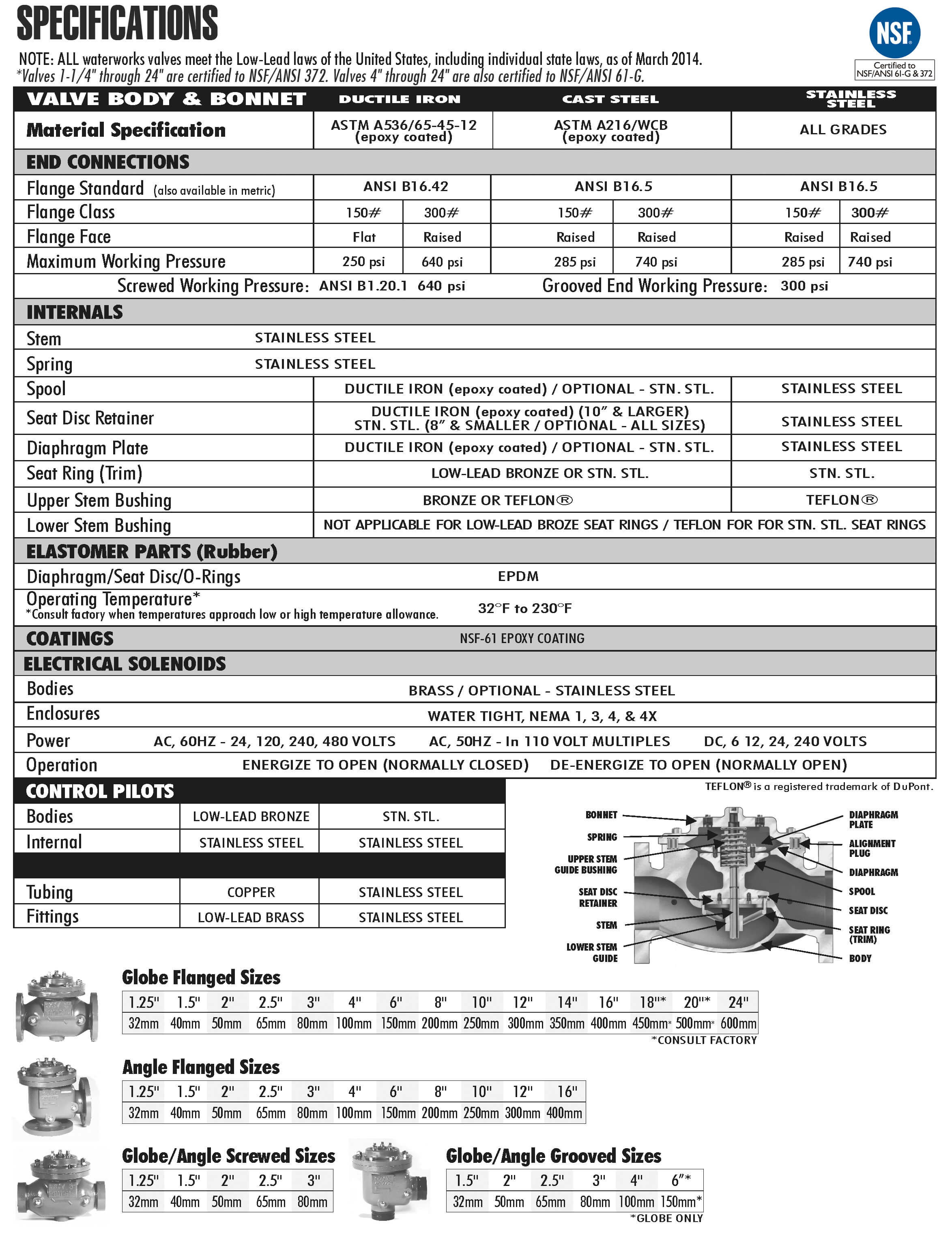
For maximum efficiency, the OCV control valve should be mounted in a piping system so that the valve bonnet (cover) is in the top position. Other positions are acceptable but may not allow the valve to function to its fullest and safest potential. In particular, please consult the factory before installing 8″ and larger valves, or any valves with a limit switch, in positions other than described. Space should be taken into consideration when mounting valves and their pilot systems.
A routine inspection & maintenance program should be established and conducted yearly by a qualified technician. Consult our factory @ 1-888-628-8258 for parts and service.
When Ordering please provide:
Series Number – Valve size – Globe or Angle – Pressure Class – Screwed, Flanged, Grooved – Trim Material – Adjustment Range – Pilot Options – Special needs / or installation requirements.