


The OCV Pressure-Reducing Valve is used in many applications worldwide. The primary function of the 127 series is to reduce a greater upstream pressure to a lesser, more manageable downstream pressure, operating without regard to either upstream supply or downstream demand.
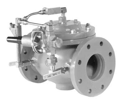
Regardless of the source of high pressure, the 127-3 reduces that pressure to a constant discharge pressure, despite fluctuations in the demand or inlet pressure. Here, a parallel valve arrangement is used to handle a wide range of demand.
(see Sizing Pressure Reducing Valves)
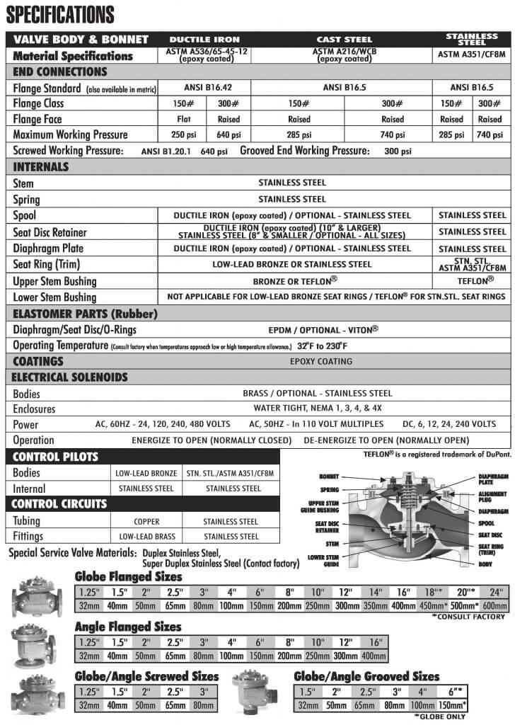
Pilot Materials
Low-Lead Bronze
Stainless Steel
Spring Ranges
5-30, 20-80, 20-200, 100-300 psi
Pilot Materials
Stainless Steel
Spring Ranges
200-750 psi
The Model 1340 & 2420 Pressure Reducing Pilot controls the amount of pressure in the upper chamber of the main valve (hence, the degree of opening or closing of the main valve). The downstream system pressure is sensed under the pilot to close, increasing the amount of pressure in the upper chamber of the main valve causing it to close a proportionate amount to maintain a constant discharge pressure. As the downstream pressure decreases, the pilot begins to open, allowing the pressure in the upper chamber of the main valve to decrease, causing the main valve to open. This is a constant modulating action compensating for any change in downstream system pressure.
For the most comprehensive procedure in sizing pressure reducing valves, it is best to use our ValveMaster software or the Performance Charts in the Engineering Section of the OCV catalog. In the absence of these, the following procedure will get you where you need to be, and enable you to avoid the most common error in sizing PRV’s: an oversized valve.
The following procedure takes both factors (flow rate/pressure drop) into account through the use of the flow coefficient, or Cv. The theory is simple: for best results, a PRV should be sized to operate between 10% and 90% of its capacity, or in other words, between 10% and 90% of its wide open Cv. It is a four-step procedure:
Calculate Cv Minimum
Q Minimum = Minimum anticipated flow, GPM
S = Specific gravity of fluid (water = 1.0
P1 = Inlet pressure at Q minimum, psi
Ps = Desire outlet pressure, psi

Calculate Cv Maximum
Q Max. = Maximum anticipated flow, GPM
P2 = Inlet pressure at Q maximum, psi
Ps = Desired outlet pressure, psi
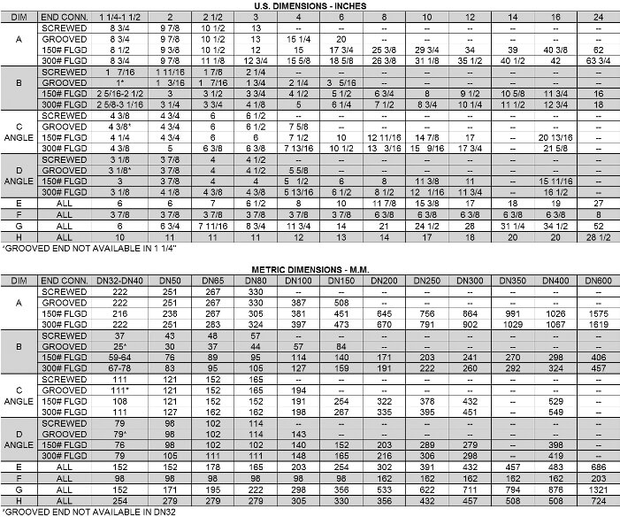
From the table, find the size that includes both the Cv min. and Cv max. you have calculated in either the globe or angle valve column.
From the table check that the velocity (GPM) at the calculated Q max. does not exceed 25 ft/sec.
Occasionally, the flow range is so wide that both the Cv min. and Cv max. will not fit in the proper range for any one size valve. In such cases, a parallel valve installation, with a smaller valve by passing around a larger one, should be given strong consideration. The valves should be sized so that:
Pressure reducing valves are, by their application, subject to pressure differentials that may induce cavitation. Often when these conditions exist, it may be only on an intermittent basis, causing minimum concern for valve deterioration.
Charts that index only inlet and outlet pressures cannot accurately predict this complex phenomenon. The easiest way to predict cavitation is to let us do the calculation. Simply fax, e-mail or call us and we will provide a graphical analysis and a solution, often simpler and less costly than the classic one: that of using two valves in series.
Provide us:
By combining various control pilots, multiple valve functions can be performed on a single Series 127 Pressure Reducing Valve. To find the combination function valve, select the desired features and then the model number.
This chart shows only a sample of those most often specified valves. Consult the factory for specific data on the model you selected.
Combination valves can often reduce or eliminate other equipment. Example: If the system requires a Pressure Reducing Valve and a Check Valve, the check feature can be added as a function of the PRV, Model 127-4.
When valve outlet pressure requires the model 2420 High Pressure Reducing pilot, an HP is added to the end of the model number. Example: Standard model 127-3 (outlet ranges from 5 – 300 psi) Model 127-3HP (outlet ranges 200-750 psi)
Most valves listed in this guide can be equipped with an intregral Low Flow By-pass regulator, an LF is added to the end of the model number. Example: Model 127-3 with low flow by-pass is 127-3LF. Valve sizing is an important aspect in correct use of this feature.
For maximum efficiency, the OCV control valve should be mounted in a piping system so that the valve bonnet (cover) is in the top position. Other positions are acceptable but may not allow the valve to function to its fullest and safest potential. In particular, please consult the factory before installing 8″ and larger valves, or any valves with a limit switch, in positions other than described. Space should be taken into consideration when mounting valves and their pilot systems.
A routine inspection & maintenance program should be established and conducted yearly by a qualified technician. Consult our factory @ 1-888-628-8258 for parts and service.
When Ordering please provide:
Series Number – Valve size – Globe or Angle – Pressure Class – Screwed, Flanged, Grooved – Trim Material – Adjustment Range – Pilot Options – Special needs / or installation requirements.