


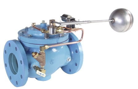
The OCV Series 8000 float control valves are designed to maintain a desired level in a tank or reservoir by opening for filling the tank when fluid is below the high level point and closing tightly when the desired level is reached.
| Model | Model Sheet | Model Sheet (metric) | Specifications | Animation | Operations Manual |
|---|---|---|---|---|---|
| Model 8000 Float Valve |

|

|

|
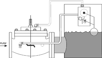
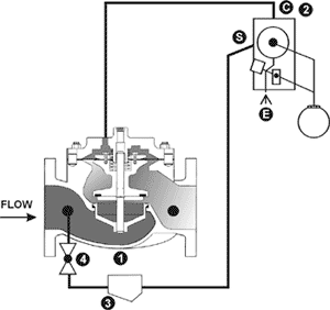
When the float is in the “down” position, the pilot port “C” is connected to the “E” port. This vents the diaphragm chamber of the main valve, allowing it to open. The tank fills through the valve until the desired high level is reached; i.e., the float reaches the “up” position. At this point, a connection is made in the pilot from “S” to “C” ports. This applies inlet pressure to the diaphragm chamber of the main valve, causing it to go fully closed.
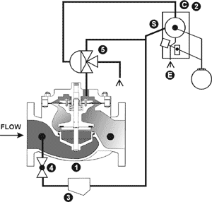
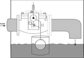
The above description applies except that the float pilot alternately vents or pressurizes the diaphragm chamber of the three-way auxiliary pilot. In relay fashion, the auxiliary pilot then vents or pressurizes the diaphragm chamber of the main valve.
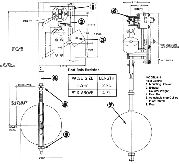
1. Mounting Bracket
2. Exhaust
3. Counter Weight
4. Float Rod, SS
5. Adjustable Stop Collars, SS
6. Pilot Control, SS
7. Float, SS
To protect the float ball from wave action within the tank, it is highly recommended that the float be installed in a stilling well. This is especially critical if the fill line exits into the top of the tank.
For maximum efficiency, the OCV control valve should be mounted in a piping system so that the valve bonnet (cover) is in the top position. Other positions are acceptable but may not allow the valve to function to its fullest and safest potential.
In particular, please consult the factory before installing 8″ and larger valves, or any valves with a limit switch, in positions other than described.
The OCV Model 814 Float Pilot is a float-actuated, three-port, rotary disc pilot designed to provide on-off action to an OCV Model 65 main valve.
It features the following:
The basic principle of operation of the 814 pilot is quite straightforward. There are three sets of ported passages in the pilot body, and matching sets in the lapped rotary disc.
While most Model 8000 valves are line sized, there are two factors that should be checked. Maximum flow rate should not exceed 25 ft/sec, in other words don’t use too small a valve. At the same time, you don’t want the valve so large that when it opens, it drops the system pressure so low that there is not enough pressure to close the valve when high level is reached. Our ValveMaster selection and sizing software covers this in detail. However, if you do not have the software, sizing within the flow limitations shown in the following table should result in satisfactory operation.
If the flow rate for a given valve will fall below the minimum, you might consider adding a pressure sustaining feature (Model 8000-3).
![]()
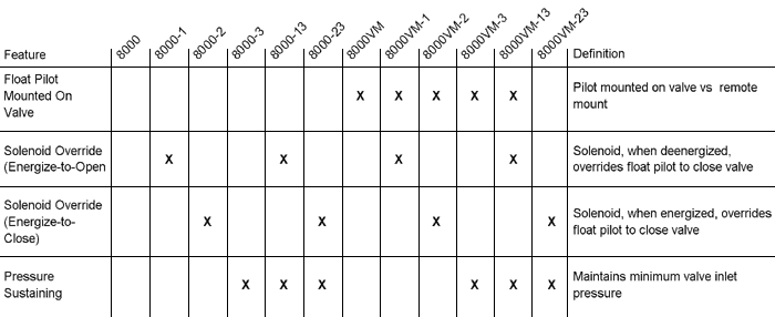 By combining various control pilots, multiple valve functions can be performed on a single Series 8000 Float Control Valve. To find the combination function valve, select the desired features and then the model number. This chart shows only a sample of those most often specified valves. Consult the factory for specific data on the model you selected.
Combination valves can often reduce or eliminate other equipment. Example: If the system requires a Pressure Sustaining function, the sustaining feature can be added as a function of the Float Valve, Model 8000-3.
For maximum efficiency, the OCV control valve should be mounted in a piping system so that the valve bonnet (cover) is in the top position. Other positions are acceptable but may not allow the valve to function to its fullest and safest potential. In particular, please consult the factory before installing 8″ and larger valves, or any valves with a limit switch, in positions other than described. Space should be taken into consideration when mounting valves and their pilot systems.
A routine inspection & maintenance program should be established and conducted yearly by a qualified technician. Consult our factory @ 1-888-628-8258 for parts and service.
When Ordering please provide:
Series Number – Valve size – Globe or Angle – Pressure Class – Screwed, Flanged, Grooved – Trim Material – Adjustment Range – Pilot Options – Special needs / or installation requirements.