


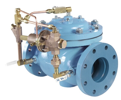
The Series 110 Differential Control Valve is designed to accurately control the pressure difference between any two points. In some systems this means the valve remains closed until pressure differential commands its opening. It is a pilot-operated, modulating type valve which controls pressure accurately and consistently at the desired setting.
| Model | Model Sheet | Model Sheet (metric) | Specifications | Animation | Operations Manual |
|---|---|---|---|---|---|
| Model 110 Differential Pressure Control Valve |

|
|

|
||
| Model 111 Differential Pressure Control Valve |
|
|
|||
| Model 101-D Differential On-Off Valve |
|
|
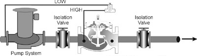
Installed on the discharge side of a pump, the valve senses high pressure at pump discharge (valve inlet) and low pressure at the pump suction. Valve modulates to hold differential pressure constant, thus assuring pump is at optimum point on its curve.
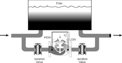
In a filtered liquid application where loss of flow cannot be tolerated, the model 110 allows flow should the filter become clogged.
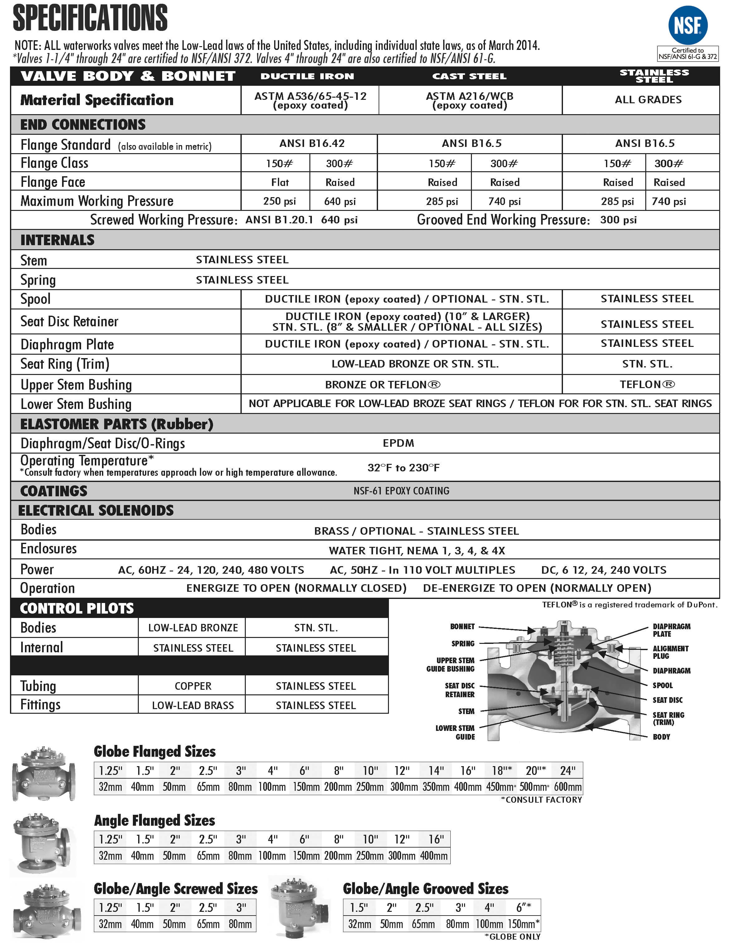
The Model 110 consists of the following components, arranged as shown on the schematic diagram:
Pilot Materials
Low-Lead Bronze
Stainless Steel
Spring Ranges
5-30, 20-80, 65-180 psi
The Model 1356 Differential Pressure Pilot controls the amount of pressure in the upper chamber of the main valve (hence, the degree of opening or closing of the main valve). The pilot senses high pressure under its diaphragm and low pressure above its diaphragm. As the differential increases above the setting of the spring (adjustable), the pilot opens, decreasing the pressure in the main valve diaphragm chamber, allowing the main valve to open a proportionate amount.
Sense line locations. High pressure sensing is typically at the main valve inlet. Low pressure can be sensed at the valve outlet or at a field installed remote location.
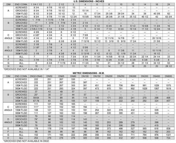
Because the Model 110 typically controls the differential pressure, that particular parameter of the sizing equation is already defined. All that remains is to ensure the valve is large enough to handle the required flow within proper velocity limits.

where: Cv = valve coefficient
Q = Maximum flow rate, gpm
sg = Liquid specific gravity (water = 1.0)
dp = Differential pressure, psig
From the chart below, pick the smallest valve that has a Cv at least equal to the value calculated and where the velocity does not exceed 25 ft/sec.
By combining various control pilots, multiple valve functions can be performed on a single Series 110 Differential Control Valve. To find the combination function valve, select the desired features and then the model number.
This chart shows only a sample of those most often specified valves. Consult the factory for specific data on the model you selected.
For maximum efficiency, the OCV control valve should be mounted in a piping system so that the valve bonnet (cover) is in the top position. Other positions are acceptable but may not allow the valve to function to its fullest and safest potential. In particular, please consult the factory before installing 8″ and larger valves, or any valves with a limit switch, in positions other than described. Space should be taken into consideration when mounting valves and their pilot systems.
A routine inspection & maintenance program should be established and conducted yearly by a qualified technician. Consult our factory @ 1-888-628-8258 for parts and service.
When Ordering please provide:
Series Number – Valve size – Globe or Angle – Pressure Class – Screwed, Flanged, Grooved – Trim Material – Adjustment Range – Pilot Options – Special needs / or installation requirements.