


The elevated tank, standpipe or storage reservoir is a common and important element found in many water distribution systems- municipal, fire protection, commercial, military and industrial.
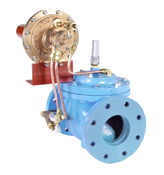
The function of the OCV Series 3330 Altitude Control Valve is accurate, automatic level control, without the use of floats or sensors. Pilot controls for the series can accommodate storage facilities up to 230 feet high, maintaining the liquid level to within inches of a predetermined set point.
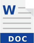
The series is offered in two basic types. The Model 3331, one-way flow is used for tank fill only. The Model 3333 allows flow both into and out of the tank.
| Model | Model Sheet | Model Sheet (metric) | Specifications | Animation | Operations Manual |
|---|---|---|---|---|---|
| Model 3331 One-Way Altitude Valve |

|
|
|||
| Model 3333 Two-Way Altitude Valve |
|
|
|||
| Model 3331-4 One-Way Altitude with Delayed Drawdown |
|
|

|
Provides automatic filling of elevated tanks or reservoirs. When the altitude control senses a drop in level below the predetermined set point, the valve opens to fill tank. When the level again reaches the set point, the valve will close. Discharge of the tank is by a separate line.
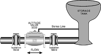
Controls both the fill and discharge cycles of a tank or reservoir. When valve inlet (system) pressure falls below tank head pressure, the altitude valve opens to feed the system. When system pressure recovers above tank head, the tank begins to refill. When the high level set point is reached, the valve will close.
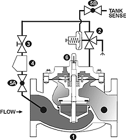
The 3331 is designed to only fill the tank. Tank head (pressure) is sensed under the diaphragm of the 3300 altitude pilot (2). When the tank head falls below the set point , the pilot shifts to vent water from diaphragm chamber of the main valve (1) to drain. This allows the valve to open and fill the tank. When the tank level again reaches the set point, the altitude pilot shifts to apply full inlet pressure to the diaphragm of the main valve, forcing the valve fully closed.
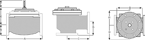
The 3331 consists of the following components, arranged as shown on the schematic diagram:
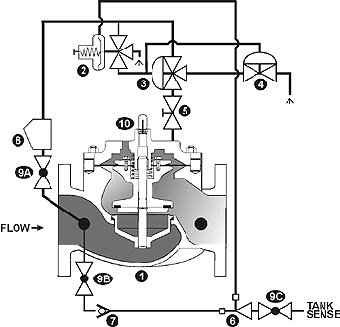
The 3333 is designed to drain and fill the tank. When the inlet (system) pressure falls below the set point of the altitude pilot (2), the pilot shifts to vent water from diaphragm chamber of the main valve (1) to drain. This allows the valve to open and let the tank feed the system. When system pressure recovers to a point higher than tank head, the tank will begin refilling. When the tank level again reaches the set point, the altitude pilot shifts to apply full inlet pressure to the diaphragm of the main valve, forcing the valve fully closed.
The 3333 consists of the following components, arranged as shown on the schematic diagram:
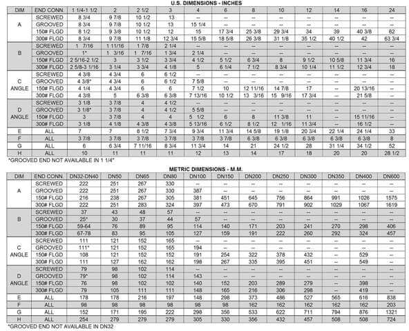
5 – 30
20 – 50
40 – 80
70 – 140
130 – 230
The altitude valve is furnished fully factory assembled except for the tank sense line. In areas where freezing temperatures are possible, the valve should be located in a vault below the frost line.
After the main valve is installed, the tank sense line must be connected at the altitude pilot. The proper installation of this sense line is critical to the efficient operation of the altitude valve. The following guidelines apply.
The altitude valve vents its diaphragm chamber to atmosphere, the volume varying according to valve size, as shown below. Provision should be made to drain off or otherwise dispose of this water.
| 1 1/4″ | 0.02 gal. | 3″ | 0.1 gal. | 10″ | 2.5 gal. | 24″ | 28.0 gal. |
| 1 1/2″ | 0.02 gal. | 4″ | 0.2 gal. | 12″ | 4.0 gal. | ||
| 2″ | 0.05 gal. | 6″ | 0.6 gal. | 14″ | 6.5 gal. | ||
| 2 1/2″ | 0.06 gal. | 8″ | 1.0 gal. | 16″ | 9.6 gal. | ||
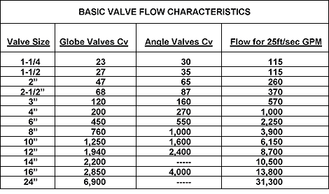
For the most comprehensive procedure in sizing Series 3330 control valves, it is best to use our ValveMaster software or the guidelines shown here in conjunction with the Performance Charts in the Engineering Section of the OCV catalog.
With rare exceptions, altitude valves are line sized. This being said, the following criteria may be applied.
The valve flow rate may be verified from the equation:
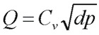 |
| where:
Q = flow rate, gallons per minute |
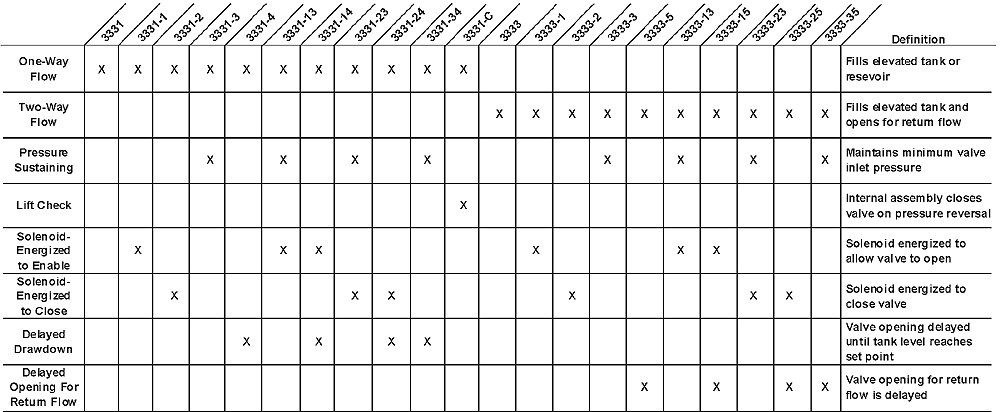
By combining various control pilots, multiple valve functions can be performed on a single Series 3330 Altitude Control Valve. To find the combination function valve, select the desired features and then the model number.
This chart shows only a sample of those most often specified valves. Consult the factory for specific data on the model you selected.
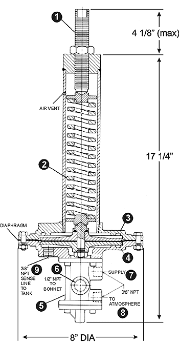
For maximum efficiency, the OCV control valve should be mounted in a piping system so that the valve bonnet (cover) is in the top position. Other positions are acceptable but may not allow the valve to function to its fullest and safest potential. In particular, please consult the factory before installing 8″ and larger valves, or any valves with a limit switch, in positions other than described. Space should be taken into consideration when mounting valves and their pilot systems.
A routine inspection & maintenance program should be established and conducted yearly by a qualified technician. Consult our factory @ 1-888-628-8258 for parts and service.
When Ordering please provide:
Series Number – Valve size – Globe or Angle – Pressure Class – Screwed, Flanged, Grooved – Trim Material – Adjustment Range – Pilot Options – Special needs / or installation requirements.