


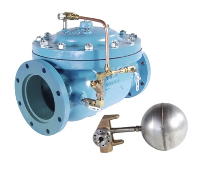
While similar to the Series 8000 On/Off Float Valves through the use of a rotary disc float control, the 8100 series provides modulating rather than on/off type action. In this way, level in the vessel can be continuously maintained within extremely narrow limits.
| Model | Model Sheet | Model Sheet (metric) | Specifications | Animation | Operations Manual |
|---|---|---|---|---|---|
| Model 8101 Modulating Float Valve |

|

|

|
||
| Model 8102 Modulating Float Valve |
|
|
|
||
| Model 8104 Modulating Float Valve |
|
|
|
||
| Model 8105 Modulating Float Valve |
|
|
|
Opens on falling level and closes on rising level. (shown with 813 pilot) Mounting of valve and pilot provides an air gap between pilot and liquid level.
Opens on rising level and closes on falling level. (shown with 812 pilot)
Opens on falling level and closes on rising level. (shown with chamber mounted 815 pilot) Typical for fuel service, floating pan tanks.
A single sense line connects the pilot (mounted above the liquid level) to the ejector on the main valve. Through the ejector, inlet pressure on the valve is supplied to the valve’s upper control chamber (bonnet) and to the pilot valve. As the level changes the pilot responds by either discharging pressure off the bonnet of the main valve thereby allowing the valve to open (falling level), or diverting inlet pressure to the bonnet, causing it to close (rising level). Level is maintained.
The float pilot (mounted at the liquid level) is connected to the ejector on the main valve which is installed on the tank discharge line. Through the ejector, inlet pressure on the valve is supplied to the valve’s upper control chamber (bonnet) and to the pilot valve. In this application the float pilot is reverse acting. As the level changes the pilot responds by either discharging pressure off the bonnet of the main valve thereby allowing the valve to open (rising level), or diverting inlet pressure to the bonnet, causing it to close (falling level). Level is maintained.
It is important to note that this application requires the use of a pump between the tank and the valve. For gravity applications the configuration of the valve will change.
Note: In either tank fill or tank discharge, valve sizes up to 6” are controlled directly by the rotary float pilot as shown here. For valve sizes 8” and larger, the float pilot operates a Model 1356 relay pilot which, in turn, operates the main valve.
For proper operation of bottom fill valves, and especially tank discharge valves, inlet pressure should be at least 5 psi greater than that of tank head. In brief, without the minimum 5 psi differential, the valve will not work. Lack of such minimum should not eliminate the valve from consideration. Refer to the Series 8100 Valve Selection Guide in this Tech Series for model numbers
After the main valve is installed the pilot sense line must be connected to the float pilot. The proper installation of the pilot line is critical to the efficient operation of the float valve. Minimum recommended size for the sense line is 1/2” OD tubing or 3/8” pipe. The pilot supply port is 3/8” NPT.
In any float pilot installation where there is periodic or continuous turbulence within the tank, consideration must be given to shielding the float from such turbulence with a stilling well. Failure to do so can result in erratic valve control
It should be understood that there is essentially no difference in the operation of the three rotary pilots used in the 8100 series. Only in a few physical characteristics do they vary.
Of the three rotary float pilots, the non-adjustable 812 is the simplest. Connected to the main valve by a sense line 3/8” NPT or larger, the 812 can be installed in the tank simply by suspending it from this line. Although the pilot is primarily designed for modulation, if high-level shutoff is desired, the 812 can be set to throttle the valve closed over the last few inches of level change. Liquid off the bonnet of the main valve is discharged by the pilot directly into the tank. The 812 is suitable for both water and fuel service, although it does not lend itself to installation in floating roof tanks.
The 813 rotary float pilot operates identically to the 812 described above, but, in addition, is equipped with an adjustable float and is constructed to provide an air gap between the float and pilot. The float assembly allows the operator to make appropriate changes in float position to accommodate specific operating conditions. The air gap feature prevents cross-connection. The (adjustable length) float arm of the 813 is counterweight-balanced for free and effortless movement.
Used primarily for fuel installations, the non-adjustable 815 rotary float pilot is specifically designed for floating roof tanks or similar installations where access to the interior of the vessel is inconvenient or impossible. The 815 installs on the exterior of the tank and, once in place, operates identically to the 812. Liquid off the bonnet of the main valve is vented back into the chamber, or, if desired, back to the outlet of the main valve.
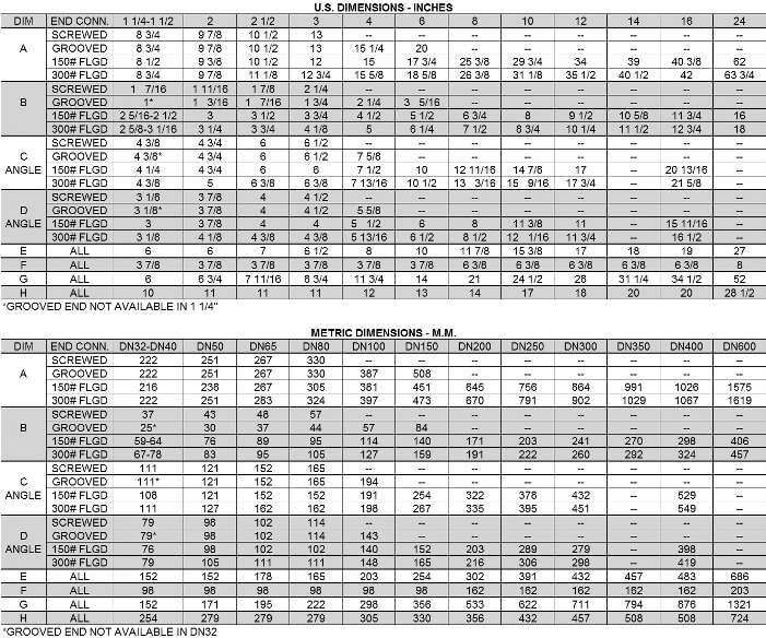
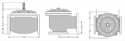
While most Series 8100 valves are line sized, there are two factors that should be checked. Maximum flow rate should not exceed 25 ft/sec, in other words don’t use too small a valve. At the same time, you don’t want the valve so large that when it opens, it drops the system pressure so low that there is not enough pressure to close the valve when high level is reached. Our ValveMaster selection and sizing software covers this in detail. However, if you do not have the software, sizing within the flow limitations shown in the following table should result in satisfactory operation.
![]()
By combining various control pilots, multiple valve functions combination function valve, select the desired features and then the model number. This chart shows only a sample of those most often specified valves. Consult the factory for specific data on the model you selected.
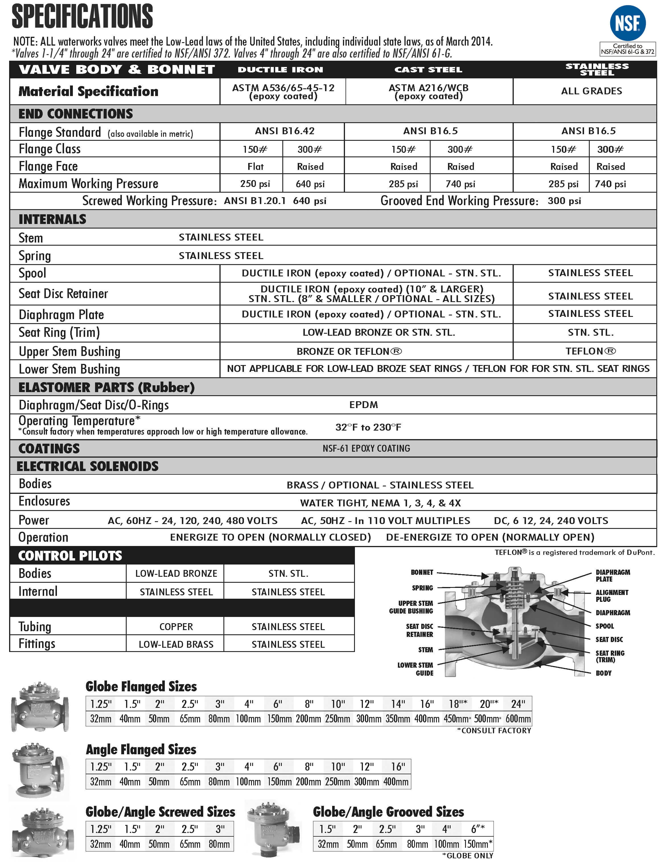
For maximum efficiency, the OCV control valve should be mounted in a piping system so that the valve bonnet (cover) is in the top position. Other positions are acceptable but may not allow the valve to function to its fullest and safest potential. In particular, please consult the factory before installing 8″ and larger valves, or any valves with a limit switch, in positions other than described. Space should be taken into consideration when mounting valves and their pilot systems.
A routine inspection & maintenance program should be established and conducted yearly by a qualified technician. Consult our factory @ 1-888-628-8258 for parts and service.
When Ordering please provide:
Series Number – Valve size – Globe or Angle – Pressure Class – Screwed, Flanged, Grooved – Trim Material – Adjustment Range – Pilot Options – Special needs / or installation requirements.