

The OCV Series 65 control valves are automatic, hydraulically actuated, diaphragm operated, rigid seal globe and angle pattern valves. These valves are designed for use in fire protection applications, including deluge, pressure control, water, foam and seawater fire protection systems. The valves consist of three major components: the body, the bonnet and the internal diaphragm assembly.
Compliance & Certification:
Consult the UL Listing Guide, FM Approval Guide, or contact Aquestia USA for a complete list of approved applications and valve sizes.
STANDARD
• Listed & approved for use in fire protection systems by various global standards
• Quick opening; Non-slam closing operation
• Drip-tight shut off to ANSI FCI 70-2 VI seat leakage class
• Simple and reliable construction
• Easy installation & maintenance
• High-grade construction materials
• Reliable pressure control
• Low pressure losses at high flow rates
OPTIONAL
• Local or remote reset
• Electric, pneumatic & electro-pneumatic control trims
• Explosion proof solenoids & trim accessories
• Seawater & foam concentrate services
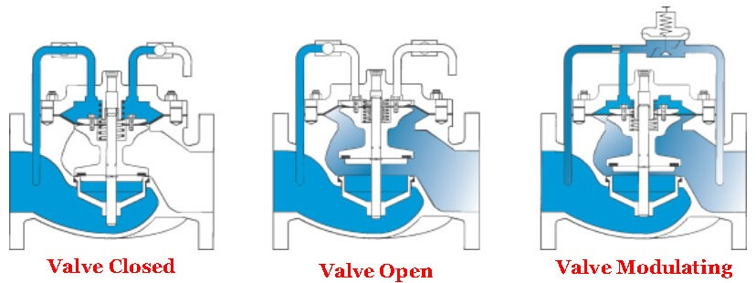
Valve Closed
When line pressure from the valve inlet is applied to the cover chamber, pressurizing the
diaphragm, the valve is closed drip-tight.
Valve Open
When cover chamber pressure is vented, the valve shifts to the fully open position.
Valve Modulating
The valve is between fully open and closed positions. The valve’s control pilot modulates the
pressure in the cover chamber, positioning the valve to control the desired pressure or flow.
FLOW CHARACTERISTICS
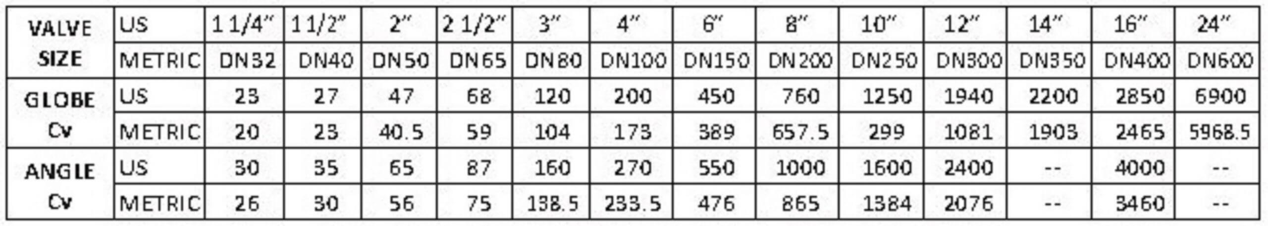

where:
Q = Flow Rate in USGPM (U.S.) or
Q = Flow Rate in cubic meters/sec (Metric)
Cv = Flow Rate in USGPM @ 1 psi pressure drop (U.S.) or
Cv = Flow Rate in cubic meters/sec @ 1 bar pressure drop (Metric) DP = Pressure Drop in psi (U.S.) or
DP = Pressure Drop in bar (Metric)
sg = Specific Gravity of line fluid
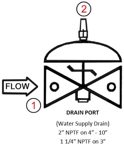
The Model 65FC consists of the following components, arranged as shown on the schematic diagram:
[1] Model 65FC Basic Control Valve: a UL Listed, hydraulically operated, diaphragm actuated globe valve which closes with an elastomer-on-metal seal.
[2] Model 155Visual Indicator Assembly: (optional) provides indication of valve position at a glance.
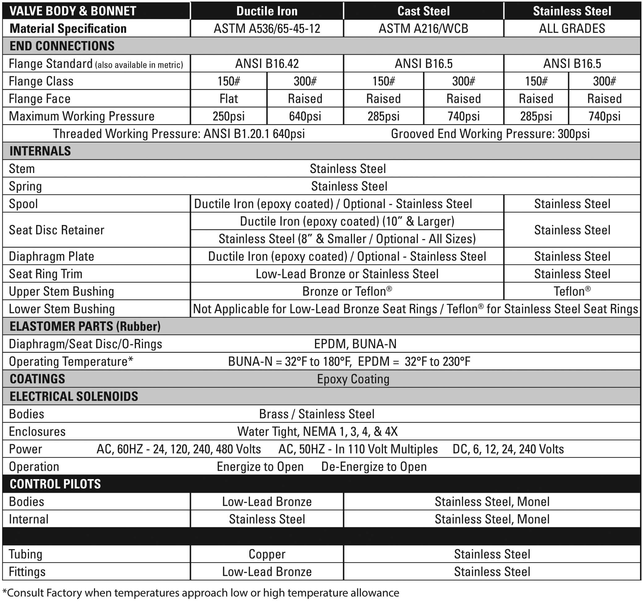
SPECIFICATIONS
Temperature:
Sizes:
End Connections:
Pressure Rating (Ductile Iron at 100°F/37.8°C):
Body & Cover Material:
Coating Material:
Optional Coating Material:
Main Valve Trim Material:
Elastomers:
Optional Components:
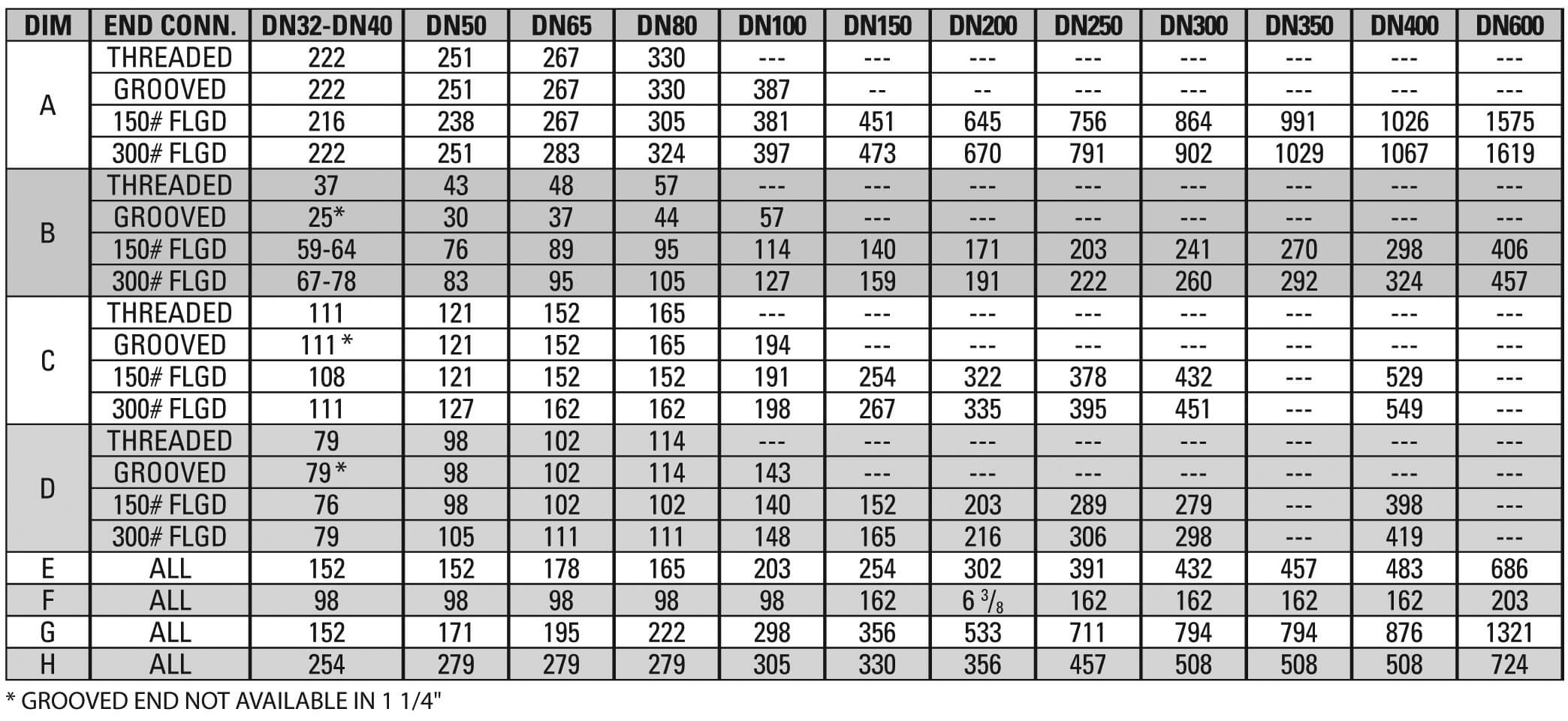
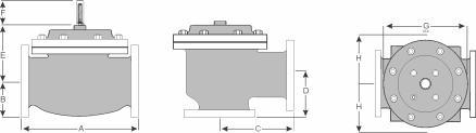
U.S. DIMENSIONS – INCHES
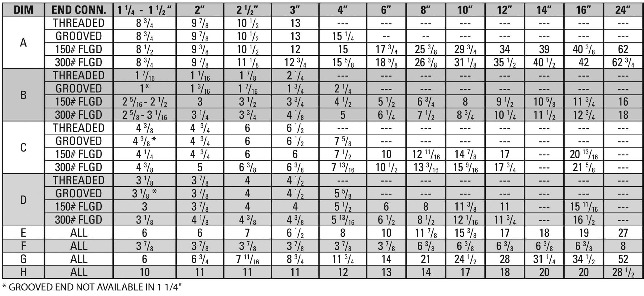
METRIC DIMENSIONS – M.M.